Green Screen Virtual Studio
Real-time Green Screen Virtual Studio is a specialized production setup used in film, television, and other setups. It involves shooting a subject or scene against a cyclorama, which is replaced with your real-time rendered image by Reality 5.5 SP1 using RealityKeyer.
Process
- Select the Example Project from the Renderers section inside the Reality Hub Launcher module.
![]()
- Select Reality 5 in the Launch With section as illustrated above.
- Click on the Launch button.
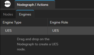
- Go to the Engines tab, drag and drop the
UE5node into the Nodegraph canvas.
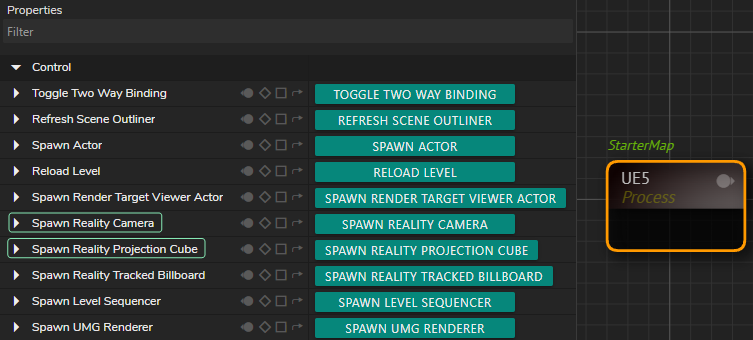
- Select the
UE5in the nodegraph canvas. - Click on the
UE5in the Nodes section. - Click on the Spawn Reality Camera and Spawn Reality Projection Cube buttons as illustrated above.

- Add
AJAInandAJAOutnodes to the Nodegraph canvas.
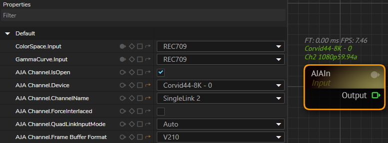
- Select your
AJAInnode properties based on your device.
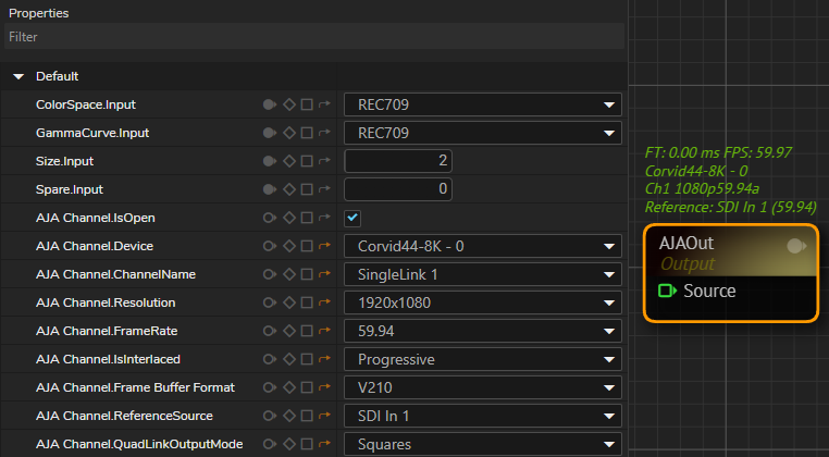
- Select your
AJAOutnode properties based on your device. - Add a Tracking Node (in our example it is the
Xyncnode) into canvas.

- Go to the
Xyncnode property, click on theEnablecheckbox.
Changing the Transform Mapping
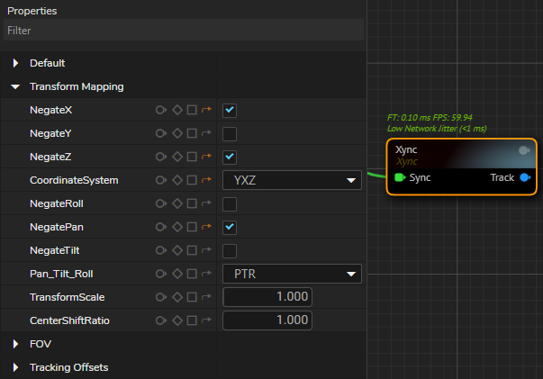
- Depending on your studio setup, you may be required to change the
Transform Mappingproperty group settings. In our example, we have to change theNegateX,NegateZ,CoordinateSystem, andNegatePanproperties, as illustrated above.
Breaking Track
In order to get Lens Distortion data from your track output, you need to utilize dynamic node approach. To do that:
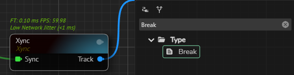
- Left click and drag the Track output of the
Xyncnode, then locate and select theBreak nos.fb.Tracknode, as illustrated above.
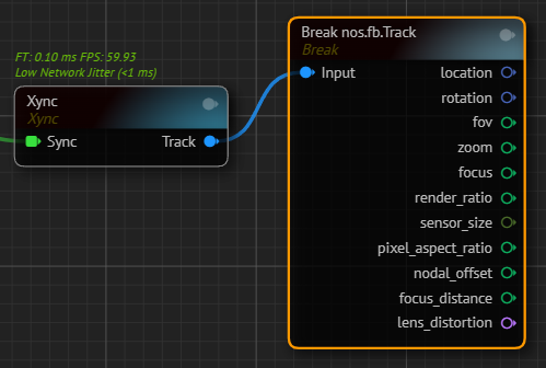
- Breaking track is complated, as illustrated above.
- Add an
Undistortnode to nodegraph canvas. - Connect the Lens Distortion output of the
Break nos.fb.Tracknode into Distortion input of theUndistortnode. - Connect the
AJAInnode's Output pin toUndistortnode's In pin.
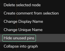
- Optionally, you can right click on the
Break nos.fb.Tracknode and select the Hide unused ping from the Node Context Menu, as illustrated above.
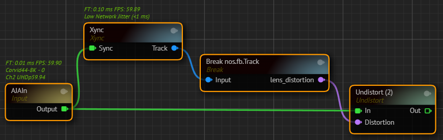
Your node network should look like in the image above.
Undistorting the image taken by your studio camera is necessary because almost every camera lens has some degree of optical distortion. On the other hand, the Cyclorama node creates a 3D shape that isn't affected by lens distortions. To make sure the Cyclorama and camera image match up correctly, it's crucial to use the undistortion process.
- Add a
Cycloramanode to nodegraph canvas. - Connect the Out output pin of the
Undistortnode to Video input of theCycloramanode. - Connect the Track output of the
Xyncnode into Track input of theCycloramanode. - Add two
Distortnodes to canvas. - Connect the Render output pin of the
Cycloramanode to In input pin of the firstDistortnode. - Connect the Mask output pin of the
Cycloramanode to In input pin of the secondDistortnode. - Connect the Lenst Distortion output pin of of the
Break nos.fb.Trackto Distortion input of the twoDistortnodes.
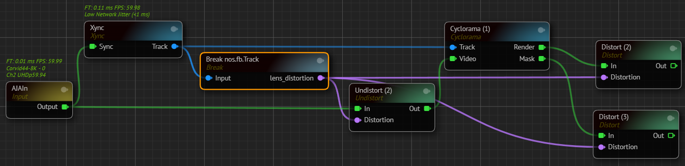
Your node network should look like in the image above.
- Add
RealityKeyernode to nodegraph canvas. - Connect
AJAInnode's Output pin toRealityKeyernode's Input pin. - Connect Out output pin of the first
Distortnode to Clean Plate input of theRealityKeyernode. - Connect Out output pin of the second
Distortnode to Clean Plate Mask input of theRealityKeyernode. - Create an
Undistortnode. - Connect the Output pin of the
RealityKeyerinto In input pin of theUndistortnode. - Connect the Lenst Distortion output pin of of the
Break nos.fb.Trackto Distortion input of the thirdDistortnode's Distortion input pin.
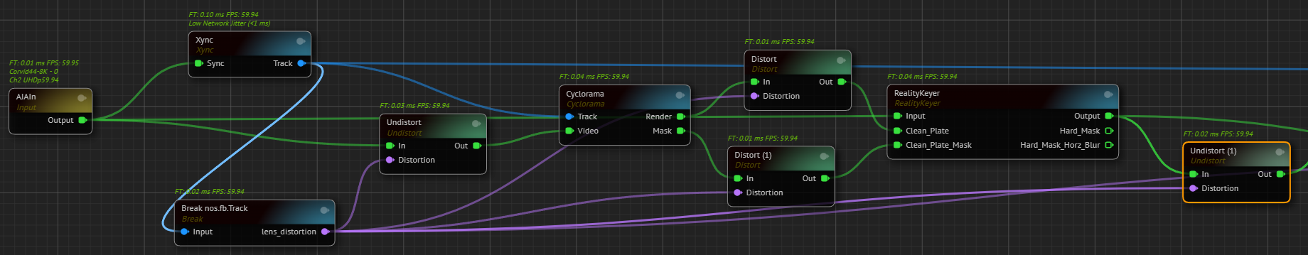
Your node network should look like in the image above.
- Connect the Out output pin of the
Undistortnode into Video Input pin of theUE5node. - Create a
CompositePassesnode. - Connect the Scene output pin of the
UE5node into Render input of theCompositePassesnode. - Connect Out output pin of the
RealityKeyernode into Video input of theCompositePassesnode. - Connect the Lenst Distortion output pin of of the
Break nos.fb.Trackto Distortion input of theCompositePassesnode. - Add a
Resizenode to nodegraph canvas. - Connect the
CompositePassesnode's Output pin intoResizenode's Input pin. - Add a
Mixernode to nodegraph canvas. - Connect the
Resizenode's Output pin to the Channel1 input pin of theMixernode. - Connect the
Multiviewerputput pin of theMixernode into Source input pin of theAJAOutnode.
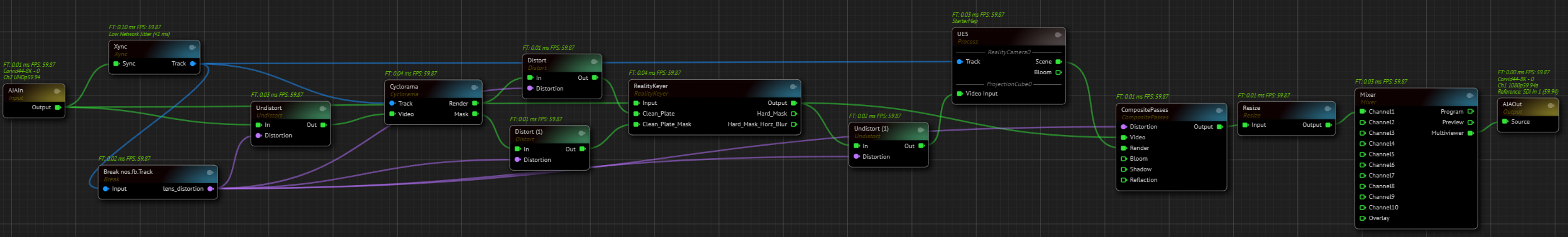
Your node network is complated, as shown above.
Examples