Creating Graph Network
In this section, we'll create a node network.
-
Launch Project and Add UE5 Node:
- Launch your desired project.

Adding UE5 Node to Canvas - Add a UE5 node to the nodegraph canvas.
- Navigate to the Nodes panel and select UE5.
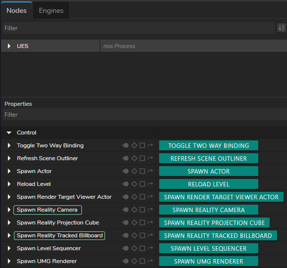
Spawning Reality Camera & Reality Track Billboard - Go to the Properties panel and click on the Spawn Reality Camera and Spawn Reality Tracked Billboard functions.
-
Add AJAIn and AJAOut Nodes:
- Add AJAIn and AJAOut nodes.
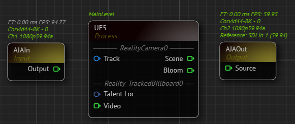
AJA Nodes with their Selected Details - Select your device details.
Adding Track Sources
- Add Tracking Nodes:
- Add your talent tracking and camera tracking nodes to the canvas. In our example, we use the Xync node for camera tracking and the FreeD node for talent tracking.
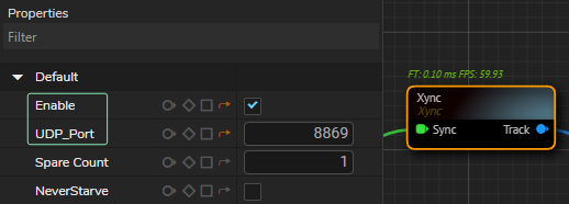
- Enable your tracking nodes by clicking on the Enable property under the Default property group and define your UDP Port.
- Connect Tracking Nodes:
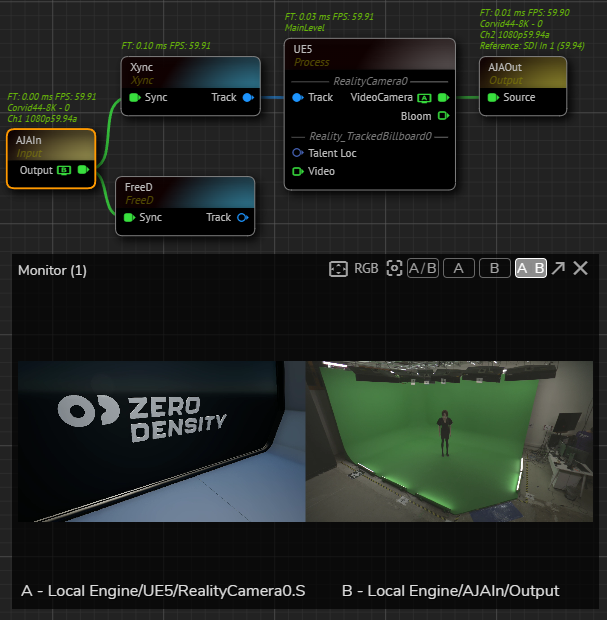
- Connect the Track output pin of the Xync node to the Track input of the UE5 node.
- Connect the Scene output pin of the UE5 node to Source input pin of the AJAOut node. This connection lets you run the nodegraph and verify the Unreal scene and AJA input.
- Use the Advanced Preview Monitor on the AJAIn node's Output pin to check if you're receiving the correct signals.
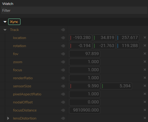
- Check each track node for data flow by using Property Watch Panel. If corresponding nodes shows all zeros, re-check and verify your port number, track network connection, or device.
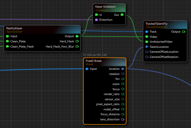
- Use Break Nodes:

- Add two Break nodes.
- Connect the Track outputs to your track nodes (In our case it is Xync and FreeD) into their Input pins. This extracts all data from the track nodes.
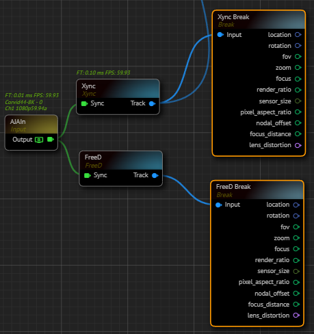
- Rename break nodes for better organization (e.g., Xync Break for camera tracking and FreeD Break for talent tracking).
- Add Undistort Node:
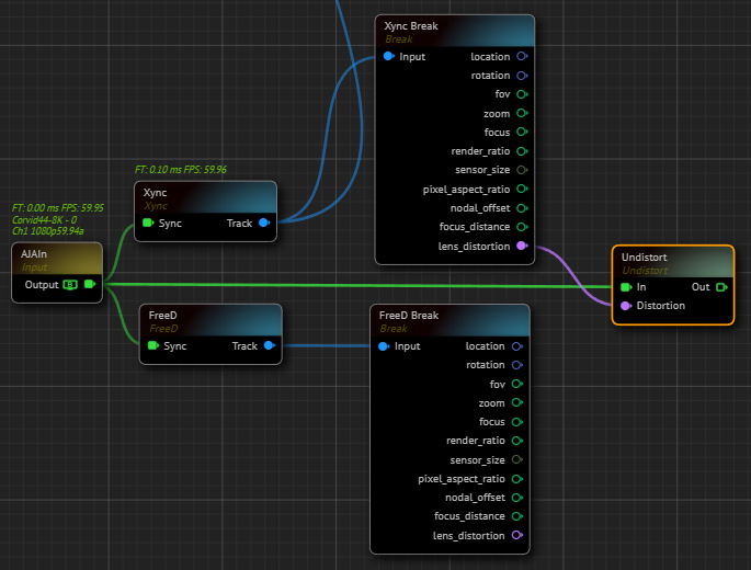
- Add an Undistort node.
- Connect the Output pin of the AJAIn node to the In input pin of the Undistort node.
- Connect the Lens Distortion output of the Xync node to the Distortion input of the Undistort node.
Cyclorama and Keyer
- Add Cyclorama Node:
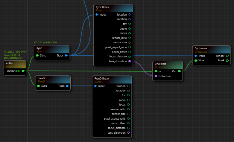
- Add a Cyclorama node to the nodegraph canvas.
- Connect the Track output pin of the Xync node to the Cyclorama node's Track input.
- Connect the Out pin of the Undistort node to the Video input pin of the Cyclorama node.
info
At this point, make sure that there's no talent in your physical cyclorama since next steps involves taking clean plate.
-
Configure Cyclorama:
- Modify the Cyclorama node's properties based on your studio setup (e.g., Geometry and Smoothness).
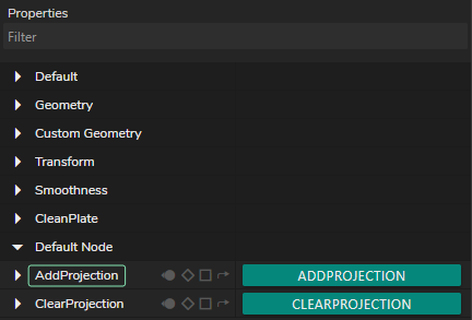
- Capture a clean plate by clicking on the Add Projection function.
- Add Distort Nodes:
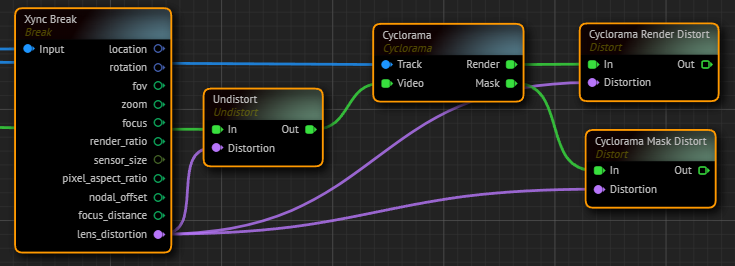
- Add two Distort nodes to the nodegraph canvas.
- Rename Distort nodes for better organization (e.g., Cyclorama Render Distort and Cyclorama Mask Distort).
- Connect the Render output pin of the Cyclorama node to the Cyclorama Render Distort node.
- Connect the Mask output pin of the Cyclorama node to the Cyclorama Mask Distort node.
- Connect the Xync Break node's Lens Distortion output to the Distortioninput of both Cyclorama Distort nodes.
- Add Reality Keyer Node:
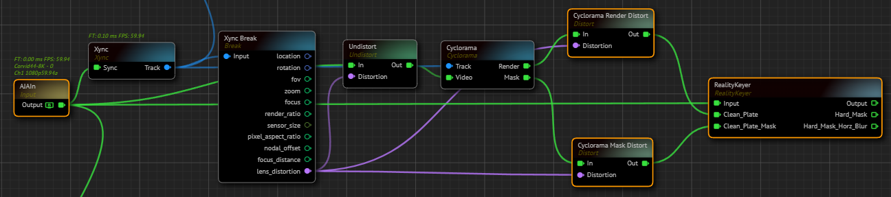
- Add a Reality Keyer node to the canvas.
- Connect the AJAIn node's Output pin to the Reality Keyer's Input pin.
- Connect the Cyclorama Render Distort node's Out output pin to the Clean Plate input pin of the Reality Keyer node.
- Connect the Cyclorama Mask Distort node's Out output pin to the Clean Plate Mask input pin of the Reality Keyer node.
Exposing Engine Properties as Inputs
- Expose Reality Camera Properties:
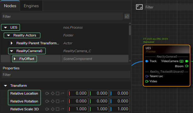
- Select the UE5 from the Nodes section, expand Reality Actors > Reality Camera, and select FlyOffset.
- Go to the Properties panel, expand the Default property group.
- Right-click on the Relative Location and select Show as input.
- Right-click on the Relative Rotation and select Show as input.
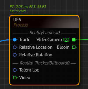
Your UE5 node should look like in the image above.
Casting with Dynamic Nodes
- Cast Talent Location:
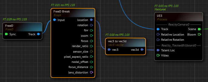
- Go to the FreeD Break node, left-click and hold your mouse over the Location output pin, then drag and drop it to open the Node Creation Menu.
- Find vec3 to vec3d and select it. This creates a vec3 to vec3d node.
- Connect the vec3d output pin of the vec3 to vec3d node to the Talent Loc input pin of the UE5 node. This allows the Tracked Billboard to receive X, Y, Z location data from your talent tracking (in our case, the FreeD node).
- Create Rotation Offset:
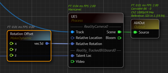
- Add a Make node to the canvas and rename it as Rotation Offset.
- Connect the Output pin of the Rotation Offset node to the Relative Rotation input of the UE5 node. This allows offsetting the relative rotation of the Reality Camera's pan, tilt, and roll. The Rotation Offset node's X property represents roll, Y represents tilt, and Z represents pan.
- Create Location Offset:
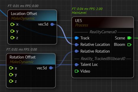
- Add a Make node to the canvas and rename it as Location Offset.
- Connect the vec3 output pin of the Location Offset node to the Relative Location input of the UE5 node. This allows offsetting the relative location of the Reality Camera. The Location Offset node's X property represents the X direction, Y represents the Y direction, and Z represents the Z direction.
Tracked Talent Fly Node
- Add Tracked Talent Fly Node:
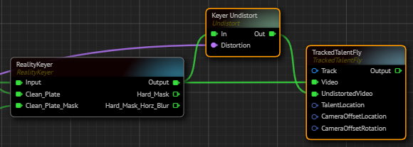
- Add a Tracked Talent Fly node to the canvas.
- Add an Undistort node to the nodegraph canvas and rename it as Keyer Undistort.
- Connect the Lens Distortion output pin of the Xync Break node to Distortioninput of the Keyer Undistort node.
- Connect the Output pin of the Reality Keyer node to In input pin of the Keyer Undistort node.
- Connect the Output pin of the Reality Keyer node to Video input of the TrackedTalentFly node.
- Connect the Out pin of the Keyer Undistort to UndistortedVideo input of the TrackedTalentFly node.
- Connect the Track output pin of the Xync node to the Track input of the TrackedTalentFly node.
- Connect the Location output pin of the FreeD Break node to the TalentLocation input of the TrackedTalentFly node.
- Add Location and Rotation Offset Breaks:
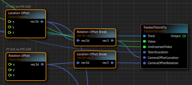
- Add a vec3d to vec3 node to the canvas and rename it as Location Offset Break.
- Connect the Location Offset node's vec3d output to the Location Offset Break node's vec3d input.
- Connect the vec3 output of the Location Offset Break node to the CameraOffsetLocation input pin of the TrackedTalentFly node.
- Add another vec3d to vec3 node and rename it as Rotation Offset Break.
- Connect the Rotation Offset node's vec3d output to the Rotation Offset Break node's vec3d input.
- Connect the vec3 output of the Rotation Offset Break node to the CameraOffsetRotation input pin of the TrackedTalentFly node.
Finalizing Setup
- Add CompositePasses Node:
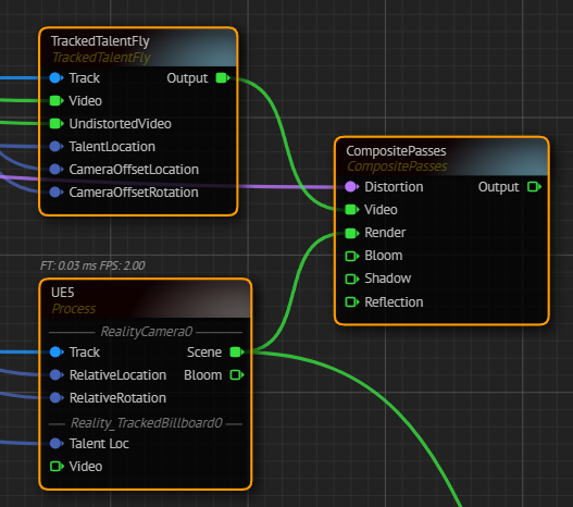
- Add a CompositePasses node to the canvas.
- Connect the Xync Break node's Lens Distortion output pin to the CompositePasses node's Distortion input pin.
- Connect the Scene output pin of the UE5 node to the CompositePasses node's Render input pin.
- Connect the TrackedTalentFly node's Tracked Talent Fly pin to the Video input of the CompositePasses node.
- Add Mixer Node:
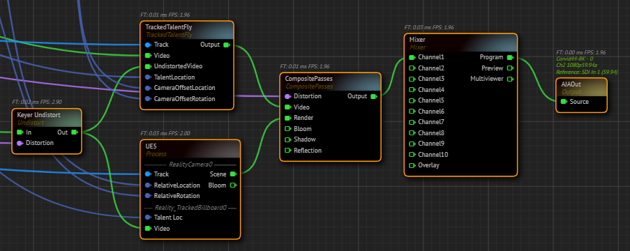
- Add a Mixer node to the canvas.
- Connect the Output pin of the CompositePasses node to the Channel1 input of the Mixer node.
- Connect the Program output pin of the Mixer node to the Source input pin of the AJAIn node.
- Connect the Keyer Undistort node's Output pin to Output input pin of the UE5 node.
- Right-click on the Program output pin of the Mixer node and go to Monitor > Channel - A.
info
At this point, depending on your studio setup, you may need to map your transform (also known as negating) and adjust default values of your track nodes.
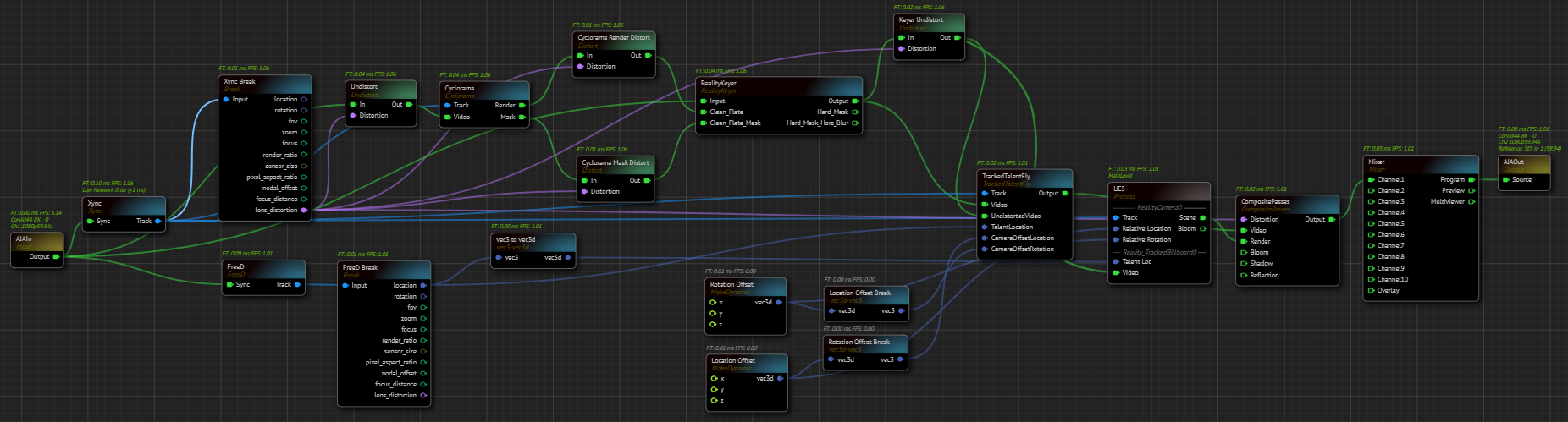
Your graph is now ready. Navigate to the Nodegraph Menu and click on the Save option.