Green Screen Virtual Studio
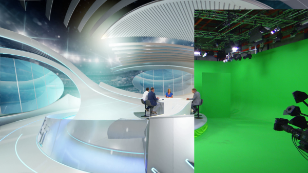
Real-time Green Screen Virtual Studio is a specialized production setup used in film, television, and other media industries. It involves shooting a subject or scene against a cyclorama, which is replaced with your real-time rendered image by Reality 5.5 using RealityKeyer.
Process
- Select the Example Project from the Renderers section inside the Reality Hub Launcher module.
![]()
- Select Reality 5 in the Launch With section as illustrated above.
- Click on the Launch button.
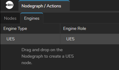
- Go to the Engines tab, drag and drop the
UE5node into the Nodegraph canvas.
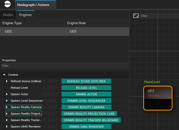
- Select the
UE5in the nodegraph canvas. - Click on the
UE5in the Nodes section. - Click on the Spawn Reality Camera and Spawn Reality Projection Cube buttons as illustrated above.

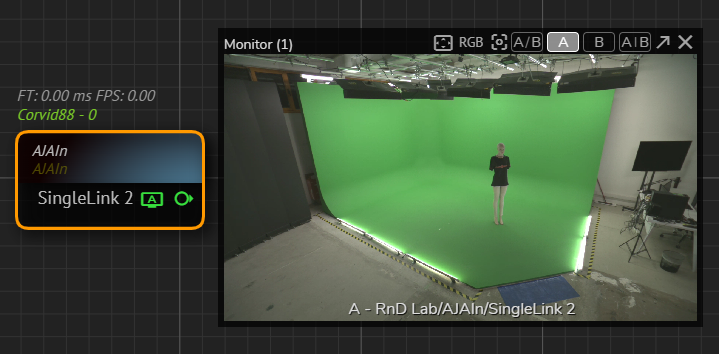
AJA Nodes- Add
AJAInandAJAOutnodes to the Nodegraph canvas. - Right-click on the
AJAInnode and select an input channel from Node Context Menu. - Right-click on the
AJAOutnode and select an output channel. - Connect the corresponding
SingleLinkoutput pin of theAJAInnode toSingleLinkinput of theAJAOutnode. (In our example we utilizedSingleLink 2andSingleLink 3)
- Right click on the
SingleLink 2and utilize APM. - Add a Tracking Node (in our example it is the
Xyncnode) into canvas.

- Go to the
Xyncnode property, click on theEnablecheckbox.
Changing the Transform Mapping
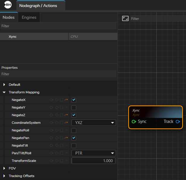
Xync Node | Transform Mapping Property GroupDepending on your studio setup, you may be required to change the Transform Mapping property group settings.
In our example, we have to change the NegateX, NegateZ, CoordinateSystem, and NegatePan properties, as illustrated above.
Breaking Track
In order to get Lens Distortion data, you need to use the Break Track node.
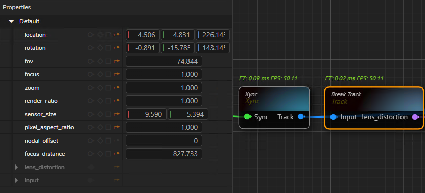
- Create a
Break Tracknode. - Connect the
Xyncnode's TrackOutputpin to theBreak Tracknode'sInputpin.
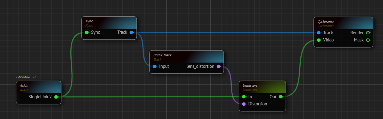
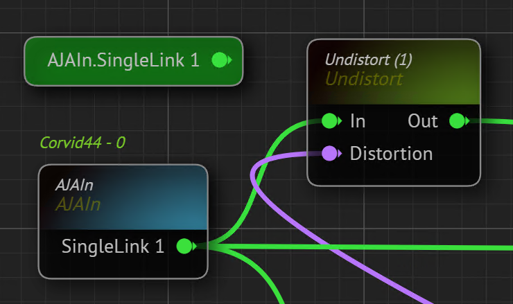
Cyclorama Node Connections- Create an
Undistortnode.
Undistorting the image taken by your studio camera is necessary because almost every camera lens has some degree of optical distortion. On the other hand, the Cyclorama node creates a 3D shape that isn't affected by lens distortions. To make sure the Cyclorama and camera image match up correctly, it's crucial to use the undistortion process.
- Go to the Properties of the
Undistortnode. - Right-click on the
Distortionproperty and select the "Show as Input" option. - Connect the
Lens Distortionoutput of theBreak Tracknode to theDistortioninput pin of theUndistortnode. - Connect the
SingeLinkoutput pin of theAJAInnode to theIninput pin of theUndistortnode. - Connect the
Outoutput pin of theUndistortnode toVideoinput of theCycloramanode. - Connect the
Trackoutput pin of theXyncnode toTrackinput of theCycloramanode.
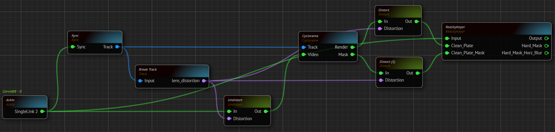
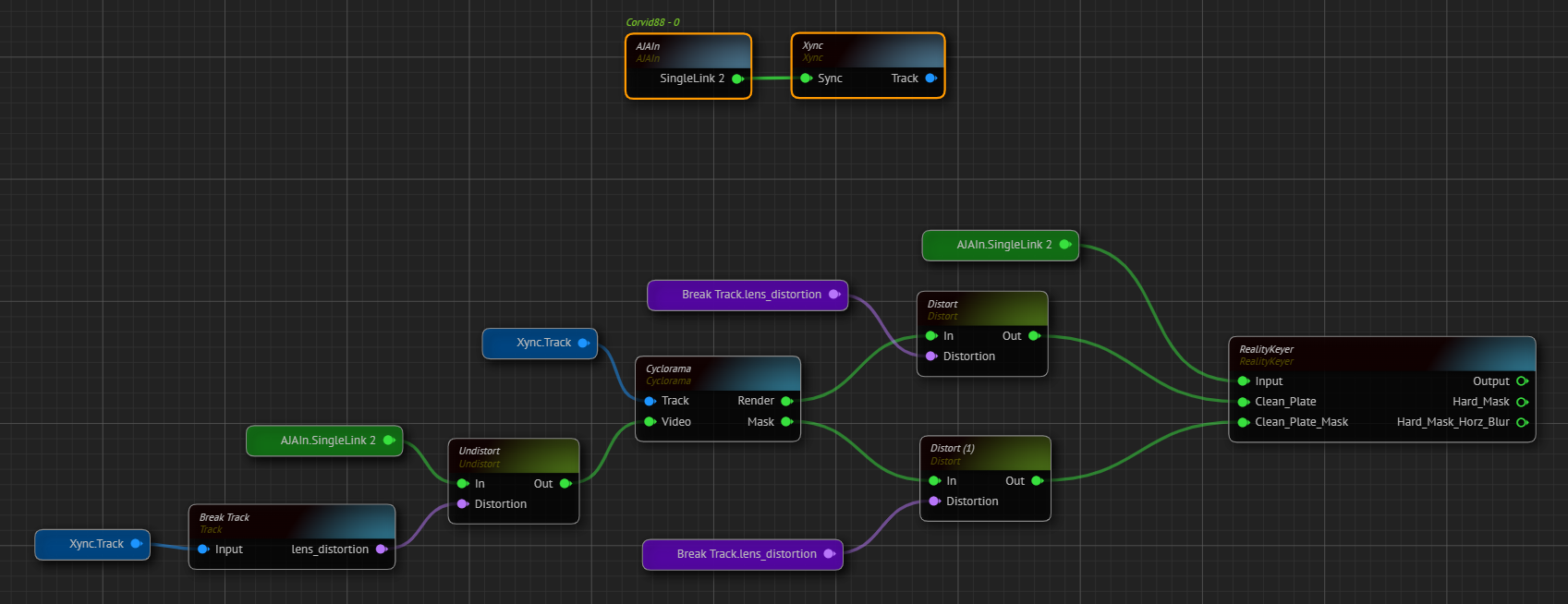
RealityKeyer Node Connections- Create a
RealityKeyernode and twoDistortnodes. - Right-click on each
Distortnode'sDistortionproperty and select the "Show as Input" option. - Connect the
Renderoutput pin of theCycloramanode to theIninput pin of theDistortnode. - Connect the
Maskoutput pin of theCycloramanode to theIninput pin of the secondDistortnode. - Connect the
Lens Distortionoutput pin of theBreak Tracknode to theDistortioninput pin of the firstDistortnode. - Connect the
Lens Distortionoutput pin of theBreak Tracknode to theDistortioninput pin of the secondDistortnode. - Connect the
Outoutput pin of the firstDistortnode to theClean Plateinput of theRealityKeyernode. - Connect the
Outoutput pin of the secondDistortnode to theClean Plate Maskthe input of theRealityKeyernode. - Connect the
SingleLink 2output pin of theAJAInnode to theInputinput pin of theRealityKeyernode.
Utilizing Portal Ping and Routing Features
At this stage, by its nature, the nodegraph gets complicated and hard to read as illustrated above. To overcome such issues, you can utilize a Portal Pin and Reroute feature.
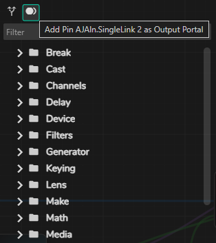
- Right-click on the
SingleLink 2output pin of theAJAInnode and select the "Copy Pin" option - Right-click on an empty space inside the Nodegraph Canvas and select & paste the previously copied pin as a portal pin as illustrated above.
The AJAIn node's SingleLink 1 output pin becomes a Portal as illustrated above and can be used anywhere inside the nodegraph with the same functionality. Portal Pin also inherits any changes in the main node.
- Connect the
SingleLink 2portal pin toIninput pin of theUndistortnode. - Right-click on an empty space in the nodegraph canvas and paste the
SingleLink 2portal pin again. - Connect the second
SingleLink 2portal pin to theSyncinput pin of theXyncnode. - By following the previous behavior, convert the
Lens Distortionoutput pin of theBreak Tracknode into the portal pin. - Paste and connect the
Lens Distortionportal pin to the corresponding input pins of nodes. - Add Rerouting between node connections you desire.
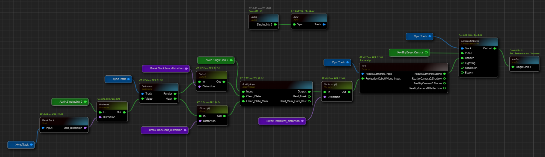
- Add a second
Undistortnode to nodegraph. - Right-click on the
Distortionproperty and select the "Show as Input" option. - Connect the
Lens Distortionoutput pin of theBreak Tracknode to theDistortioninput pin of theUndistortnode or create anotherLens Distortionportal pin and connect it to theDistortioninput pin of theUndistortnode. - Connect the
Outputpin of theRealityKeyernode to theIninput pin of theUndistortnode. - Connect the
Outoutput pin of theUndistortnode to theProjection Cube Video Inputinput of theUE5node. - Create another
Xync Trackportal pin and connect it to theReality Camera Trackinput of theUE5node. - Create a
Composite Passesnode. - Connect the
RealityKeyernode'sOutputpin toVideoinput pin of theComposite Passesnode. - Create another
Xync Trackportal pin and connect it to theTrackinput pin of theComposite Passesnode. - Connect the
RealityCamera Sceneoutput pin of theRE5node to theRenderinput of theComposite Passesnode. - Connect the
Outputoutput pin of theComposite Passesnode toSingleLinkinput pin of theAJAOutnode.