AR Graphics Workflow
Project Structure
This example uses the AR Examples project, which is part of the Reality Editor Projects collection.
Since every studio's physical layout and the specific AR graphics they will use vary, the following section creates a scenario based on our R&D studio. As a result, various settings may change in your workflow, such as the size of the Projection Cube or the transform mapping of the tracking.
This example involves opening and examining a Reality Editor project, preparing and launching a show in the Launcher module, and finally preparing the graph in the Nodegraph/Actions module.
At the end of this tutorial, you will have the entire Graph file via the nodegraph visualizer so you can copy and paste it into your nodegraph with a single click.
Before You Begin
Before you begin, we suggest you to sketch your production steps. Determine where you will display AR graphics, how your talent and other scene elements will interact with AR shadows and reflections, and how other production steps will proceed. After that, change your studio camera view to that area. This saves time in upcoming steps when fine-tuning aspects of your project such as the Projection Cube transform values and geometry, the transform and size of AR design elements, and the details of your AR Region Mask.
Opening Reality Project
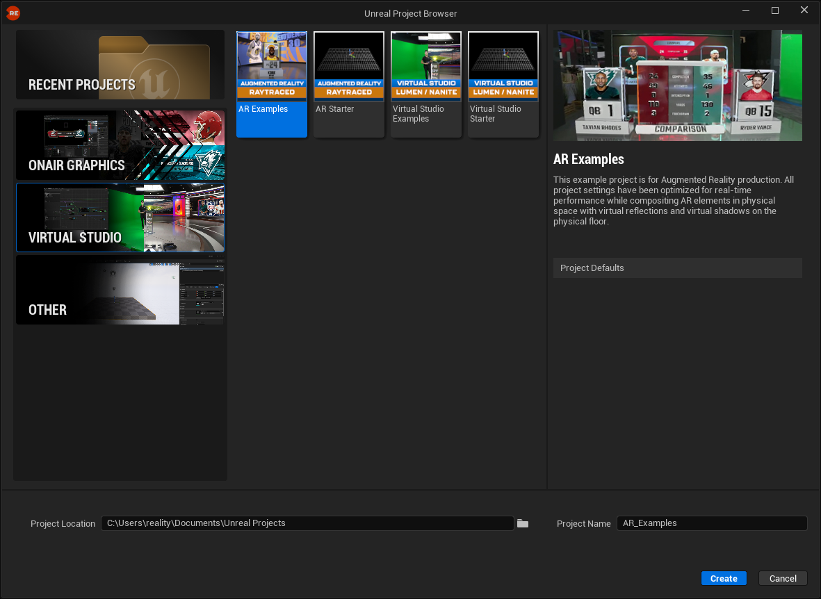
- Double-click on the Reality Editor to run it.
- Click on New Project.
- In the Project Selection menu, click on Virtual Studio and select AR Examples.
- Rename your project for better organization.
At this point, you can study the AR Examples project structure, including materials and animations.
- Save the project.
- Close the Reality Editor.
Preparing and Launching Show
- Switch to Reality Hub and navigate to the Launcher module.
- Create your Show, add your engine to the Show, assign the AR project, and select the Launch_Level map. For more details about this process, read the New Launch Configuration section.
Setting up Video IO and Tracking Data
- Switch to the Nodegraph/Actions module.
- Drag and drop the UE5 node to the canvas and select it.
- Navigate to the Properties panel, expand the Spawn Reality Camera property group, and enable the Render Shadow and Render Reflection function properties.
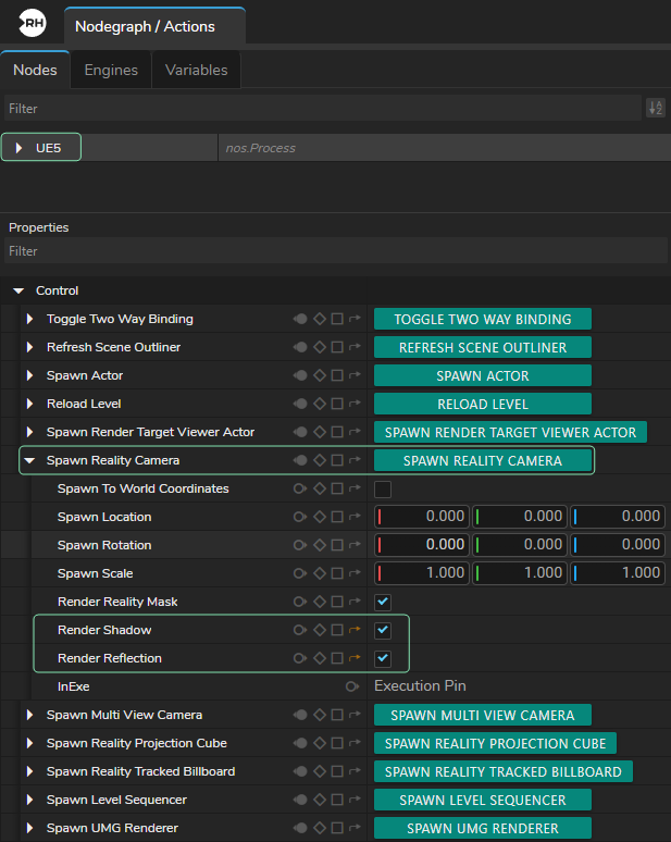
- Click the Spawn Reality Camera function button, as shown above. This spawns a Reality Camera in your scene capable of displaying AR shadows and reflections.
- Add your video I/O sources. In our case, we use AJAIn and AJAOut nodes.
- Add your tracking source. This example uses Traxis Camera Tracker, the camera tracking solution from Zero Density so we add the TraxisHubTrack node to canvas.
- Enable the tracking and connect its output to the UE5 node Track input.
- Connect the Video output of the AJAIn node to the Sync input of the TraxisHubTrack node.
Using Composite Passes
The CompositePasses node allows you to composite engine outputs such as shadows, reflections, and bloom automatically to make your AR scene realistic.
- Add a CompositePasses node to the canvas.
- Make the necessary connections from the UE5 node to the CompositePasses node.
Breaking Track with Dynamic Nodes using Automatic Casting
To get lens distortion data from the tracking, use a Break node. This is a dynamic node that involves creating connections between compatible pins to extract and manipulate specific data. This method is called Automatic Casting.
- Hover your mouse over the Track output pin of the TraxisHubTrack node.
- Left-click and drag your mouse pointer to the right, then release. This opens the Node Creation Menu.
- Find the Break node by typing its name in the filter box and select it. This breaks the track node into available data outputs embedded in the track, providing lens distortion information.
- Connect the Lens Distortion output pin of the Break node to the Distortion input pin of the CompositePasses node.
Using Mixer Node
Use the Mixer node to preview various outputs via the Advanced Preview Monitor.
- Add a Mixer node to the nodegraph canvas.
- Connect the Scene output of the UE5 node to the Channel1 input of the Mixer node.
- Connect the Video output of the AJAIn node to the Channel2 input of the Mixer node.
- Connect the Shadow output of the UE5 node to the Channel3 input of the Mixer node.
- Connect the Reflection output of the UE5 node to the Channel4 input of the Mixer node.
- Connect the Multiviewer output of the Mixer node to the Video input of the AJAOut node.
- Preview your outputs by activating the Advanced Preview Monitor on the Multiviewer output pin of the Mixer node.
Playing Item in Lino Playout
Playing your animation helps you see the final state of your design. In this example, we use the AR_Compare_AI template, a 3D scoreboard design that emerges from the floor.
- Switch to Lino Playout.
- Drag and drop the AR_Compare_AI template into the Rundown area.
- Click the Play button.
Projection Cube
Incoming video must be projected onto a surface to capture accurate reflections and shadows. The Reality Projection Cube fulfills this task.
- Switch to the Nodegraph.
- Select the UE5 node.
- Navigate to the Properties panel and click Spawn Reality Projection Cube.
- Navigate to the Nodes section, expand UE5 > Reality Actors, and select ProjectionCube0.
- Enable Debug mode by clicking on it.
Since every studio physical space and production requirement is different, you must fine-tune the rotation, location, and geometry of your Projection Cube. Ensure your AR design items are as close as possible to the convergence point of the Far (red wall texture) and Bottom (blue wall texture).
- Fine-tune your Projection Cube Transform and Reality Geometry property groups based on your studio and graphics.
AR Region Mask
The AR Region Mask allows you to display AR elements only in specific areas, ensuring virtual objects stay inside the chosen region and align correctly with the physical set.
- Activate the Advanced Preview Monitor on the Multiviewer output pin of the Mixer node.
- Select the UE5 node.
- Navigate to the Nodes panel, expand UE5 > Reality Actors > Reality Camera > FlyOffset, and select VideoCamera.
- In the Properties panel, find and expand the AR Region Mask property group.
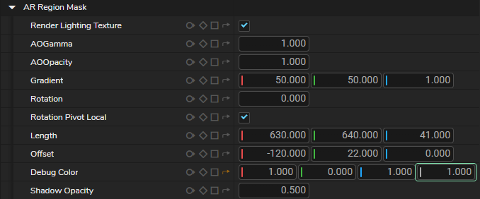
- Change the Alpha color value to 1.000. This makes the AR Region Mask visible in cyan, as illustrated above.
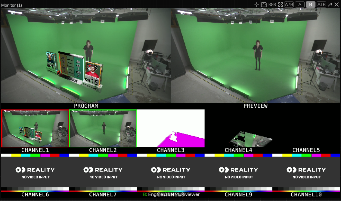
You can now modify the AR Region Mask properties based on your setup.
As the image above of the Advanced Preview Monitor shows, Channel3 displays the shadow and Channel4 displays the reflection. When you finish your setup, revert the alpha color value of the Debug Color property to 0.000.
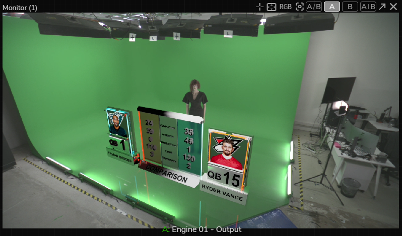
Your augmented reality setup is ready.
Graph File
You can examine the connections via the Nodegraph Visualizer or copy and paste the code directly onto your canvas to replicate the graph.
Alternatively, you directly download the Nodos Graph (*.nosa) file and import it to Reality Hub:
Additional Notes
Lights
The example scene contains two Spot Lights. Your production setup will likely use different lighting configurations, so you may need to create your own light sources through the UE5 node. For more information, refer to Reality Actor Spawning.
For more realistic results, match Unreal light settings with your physical studio lights by adjusting Kelvin values, intensity, and other light properties.
You can also enable Debug mode for lights to visualize their position, cone angle, and coverage area.
Light source geometry intersecting with shadow-casting objects may cause shadow artifacts.
If you want more control over light intensity beyond the default Unreal Editor limits:
- Select the UE5 node and expand Reality Actors.
- Select your light source. In this example, it is SpotLight0.
- In the Properties panel, expand the Light property group.
- Right-click the Intensity property and select Show as input from the context menu.
- Add a Make node to the canvas and connect its output to the Intensity input pin of the UE5 node.
You can now control the light intensity directly through the nodegraph.
Using a Second Reality Camera with UserTrack
When positioning the Projection Cube, adjusting shadows, placing lights, or checking AR elements from different camera angles, it can be useful to spawn a second Reality Camera controlled by a UserTrack node.
The UserTrack node includes a Virtual GamePad feature, allowing you to navigate freely inside the 3D scene for inspection and setup purposes.
The second camera is intended only for setup and debugging. It is not recommended for production use. After completing your setup, delete the second camera and UserTrack node through the Nodes panel before saving the final graph.