PTZ Fixed Marker Setup
Why PTZ Is Different
A PTZ camera normally changes pan, tilt, and zoom but does not translate through the studio. The calibration targets therefore require accurate, known 3D positions and suitable image coverage from camera rotation.
Create a Fixed 3D Marker
Open 3D Shapes and add a marker.
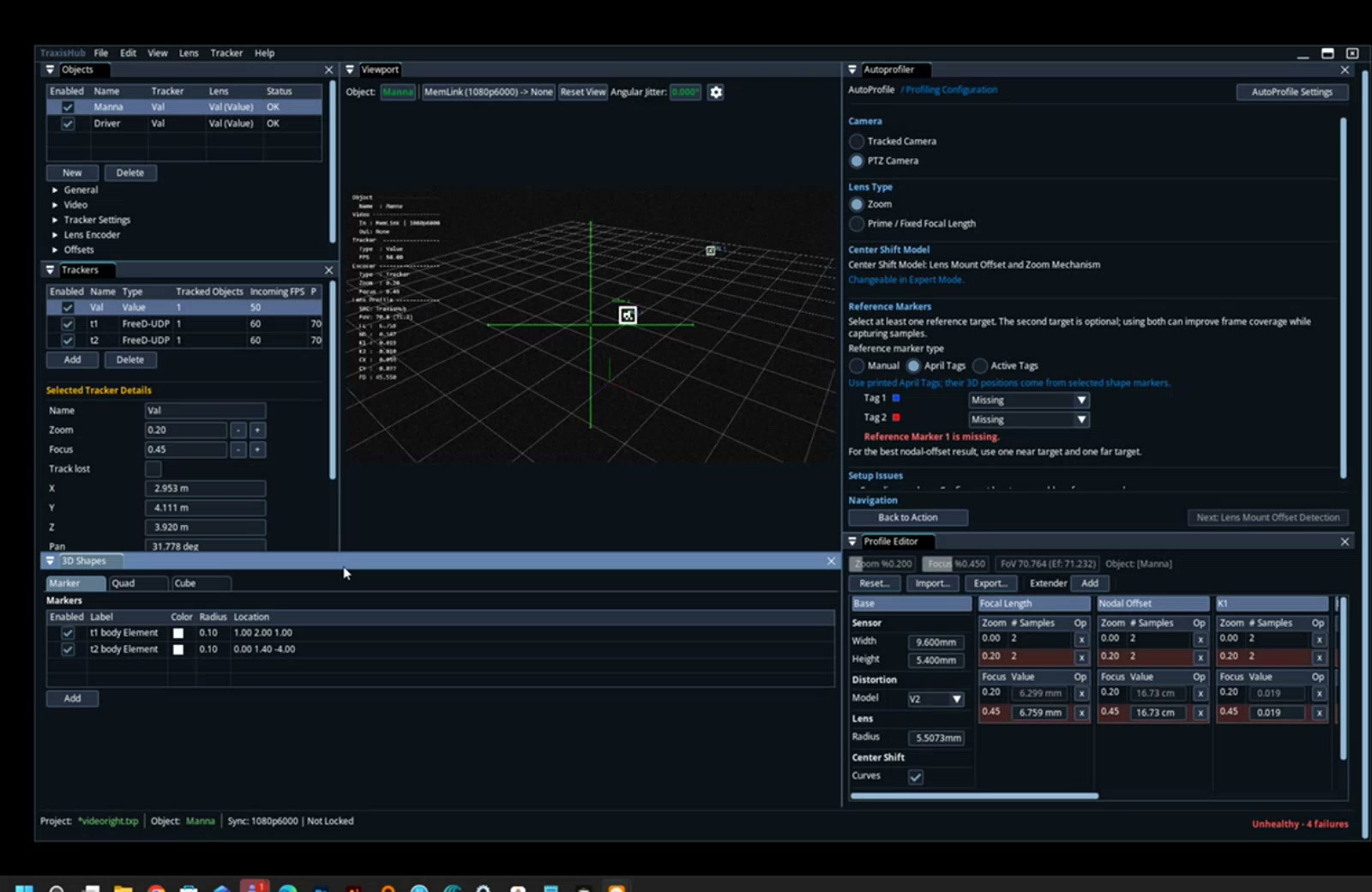
Record:
- Label.
- X, Y, Z in the project tracking coordinate system.
- Display mode.
- Enabled state.
- Corresponding physical Automatic Profiler Tags ID.
Coordinates must represent the same physical point used by the detector. Do not mix the Automatic Profiler Tags corner, edge, stand position, and Automatic Profiler Tags center.
Front Camera Helper
When direct XYZ measurement is difficult:
- Pan/tilt until the physical target center is exactly on the camera centerline.
- Measure camera-to-target distance with a laser.
- Enter that distance in the helper.
- Use Front Camera to place the marker on the current camera direction.
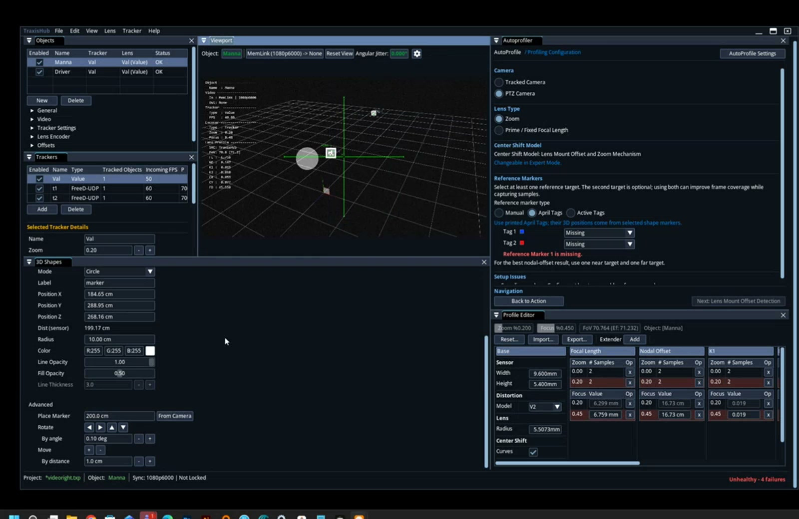
This helper is only as accurate as camera centering, the distance measurement, and the current camera pose/profile assumptions. Verify the resulting XYZ values independently when possible.
Two-Target Layout
Use one near and one far marker. Keep at least approximately 1 m physical separation and preferably enough depth variation for Nodal Offset solving. The near marker must not permanently block the far marker. Pan/tilt or place the targets with lateral/vertical separation so each complete tag can be detected.