FreeD/PTZ
You will use two markers—one far away from the camera, and one near the camera.
Physical Marker Selection
There are a few constraints when it comes to choosing a physical marker:
- The center points of the markers must be clearly distinguishable from the background.
- The Far marker must be clearly distinguishable on all zoom levels. Blurriness on the Near marker is acceptable.
- It must be possible to see both markers reasonably at the same time when the Far marker is in focus.
Based on the above, one possible way to select markers is to slightly dim the lights in the studio and use two small battery-powered LED lights.
Another way is to print a small shape with high contrast (such as a black plus sign on white paper). The shape should be small enough so that the Near marker will not obscure the Far marker.
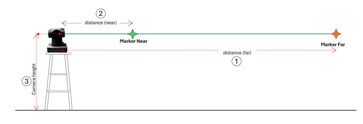
Physical Marker Placement
- Start by placing the camera on a flat, solid surface.
- Place the first marker (Far) away from the camera (6-8 meters is often sufficient) and at about the same height as the camera. If in doubt, place the marker at the general distance between the talent and the camera.
- Place the second marker (Near) as close as possible (2 meters is often sufficient) and at about the same height as the camera. The positions of the two markers and the camera should form a rough straight line.
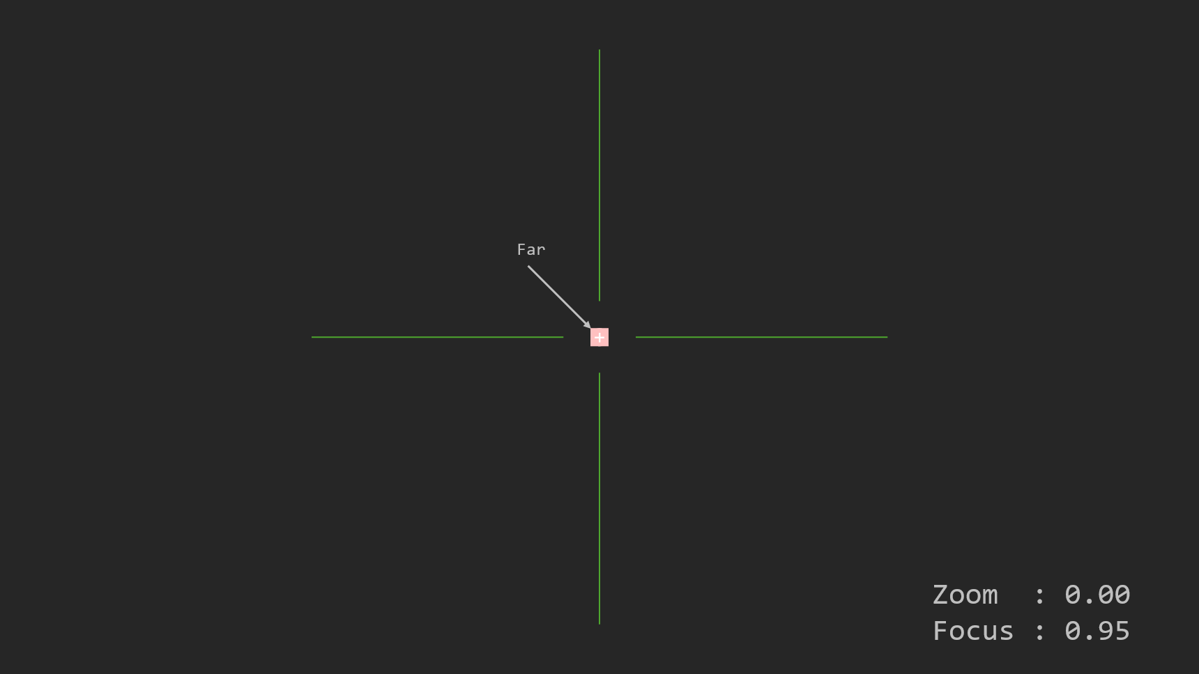
- Show the CrossHair in Traxis Hub.
- Move the Far marker to the exact center of the image.
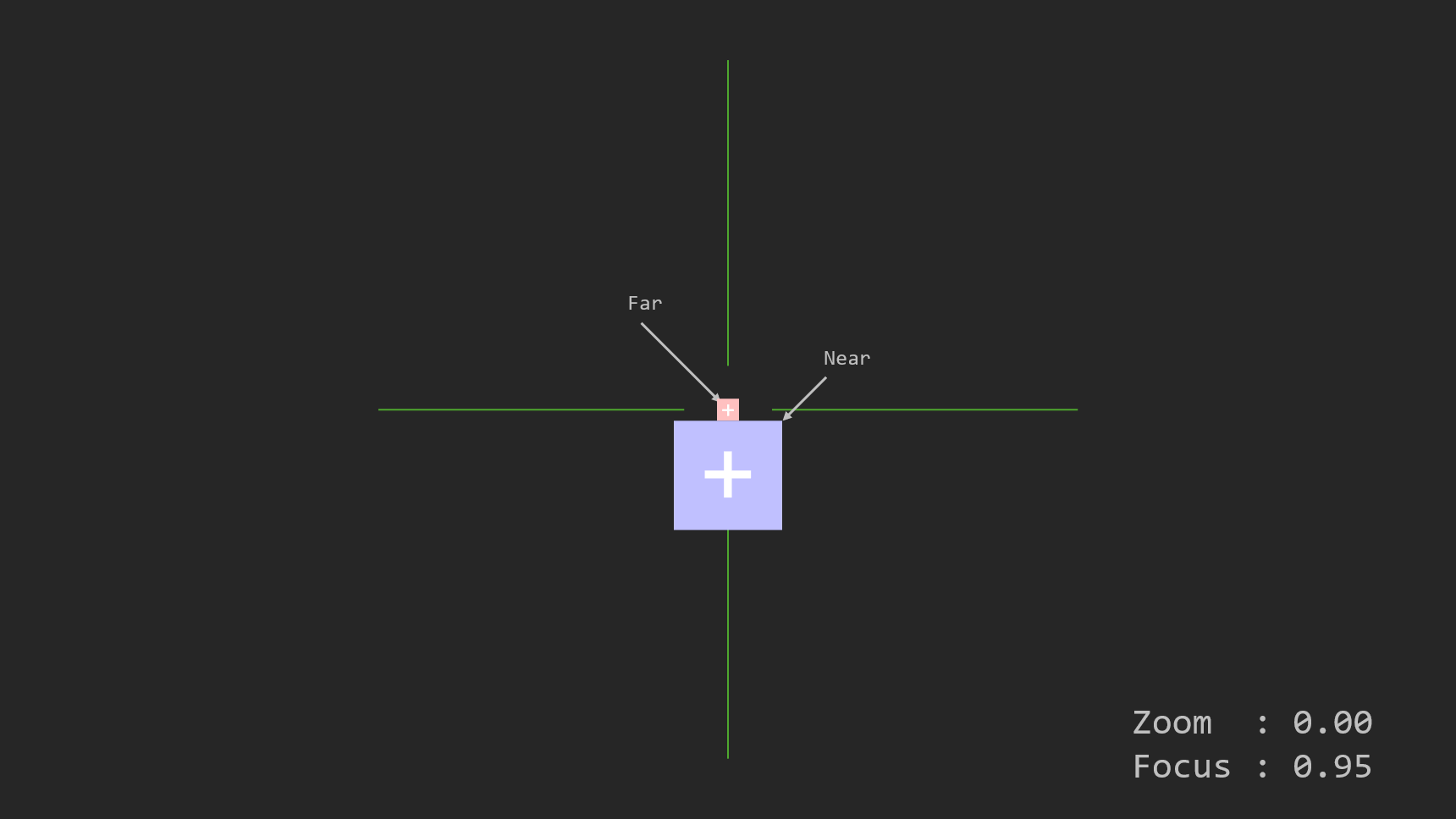
- Move the Near marker slightly below the Far marker. Both markers should be distinguishable.
- Make sure that the distances have not changed. If in doubt, measure again.
Measurement
You must measure the distances between the camera and the markers to aid marker placement.
- Obtain a measuring device—preferably a laser device, but standard measuring devices can also be used. These measurements are important, so try to measure as precisely as possible.
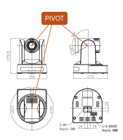
- Determine the pivot point of rotation of the camera.
- For a studio camera, the pivot point is the focal plane mark on the camera.
- For a PTZ camera, the pivot is the origin of rotation of the camera head.
- Measure three distances, all starting from the camera's pivot, and note them down:
- To the center of the first (far) marker.
- To the center of the second (near) marker.
- To the floor (i.e., the height of the pivot point).
Targeting the laser on a small marker is difficult. It is advisable to place a large solid surface just behind the marker, like a piece of paper, to aid with measurement.
Place Virtual Markers
- Show the CrossHair in Traxis Hub.
- Use mouse wheel scroll to zoom in (not lens zoom).
- Center the crosshair perfectly on the Far physical marker.
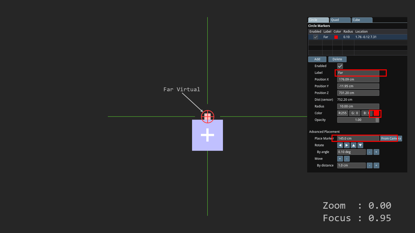
- In the Profiling Shapes panel, add a Circle marker and name it "Far".
- Set the Marker color to Red.
- Measure the distance between the camera's pivot point and the marker. Preferably, use a laser device to measure.
- Enter the measured distance and place the marker at that distance.
- Verify that the physical marker and the virtual marker overlap perfectly at the center of the crosshair.
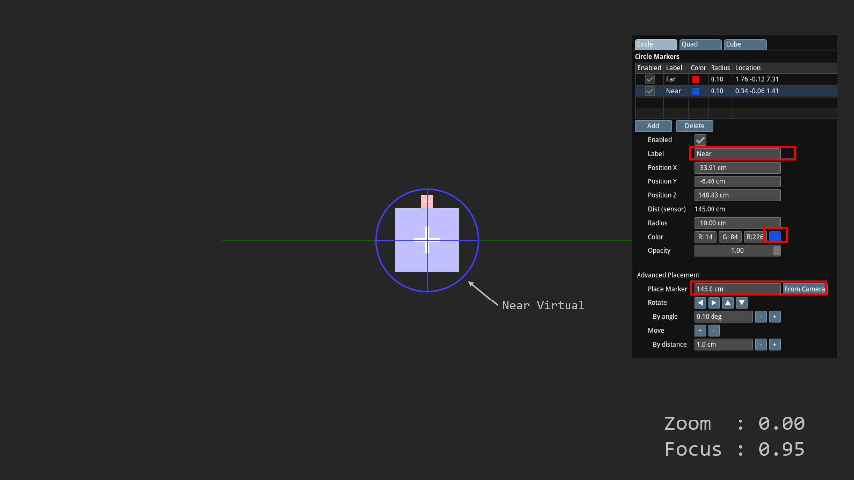
- Repeat the steps above for the Near marker:
- Center on the marker.
- Add a Circle shape, name it Near, color it blue (or another color).
- Measure distance precisely and place marker, verify overlap.
When you pan/tilt the camera to center on one marker, the other virtual marker will no longer be centered. This is because the profiling is not correct. This will be fixed in the next step.