Viewport Settings
The settings in this panel effect how the viewport is rendered.
General
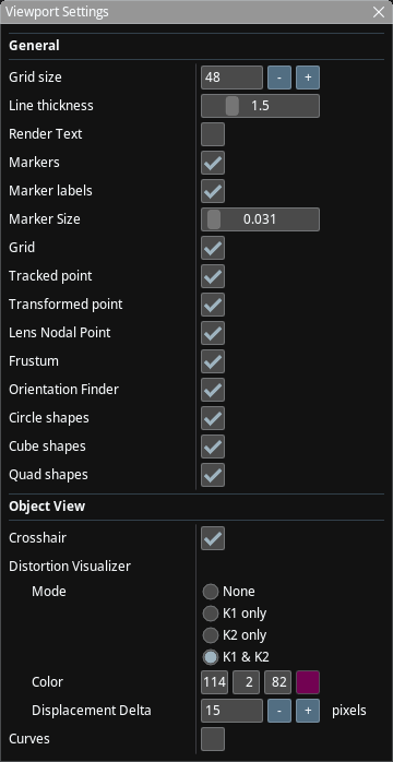
These effect Viewport in all viewing modes.
- Grid Size: The width and height of the ground grid. Each cell is 1m x 1m.
- Line Thickness: The thickness of lines rendered in the viewport
- Render Text: Whether to render 2D text in the viewport or not.
- Markers: Whether to render markers in the viewport or not. Markers are a feature of OptiTrack and also the "Simulator" tracker has three sample markers.
- Marker Labels: Show/Hide labels for markers
- Marker Size: Size of markers to be rendered. Does not effect profiling shapes.
- Grid: Render a grid that represents the studio floor.
- Tracked Point: For each tracked object, render the point that is sent from the tracker.
- Transformed Point: For each tracked object, apply the Object Position / Object Rotation tranforms (see Object Settings) to Tracked Point above and render it.
- Lens Nodal Point: For each tracked object, apply the "Nodal Offset" transform to Transformed Point above and render it.
- Frustum: Render a representation of the frustum of the object, if the object has a lens and lens encoders configured.
- Orientation finder: Render the orientation finder (X/Y/Z) on top left part of the screen and the location finder on the top right part of the screen.
- Circle/Cube/Quad shapes: Render the profiling shapes defined in the Profiling Shapes panel.
Viewport Specific
These are rendered only when the Viewport is not in "Studio View" mode.
- Crosshair: Renders a crosshair. Note that the crosshair isn't rendered if the image is moved. Double-clicking the viewport reverts all image move operations.
- Distortion Visualizer: Controls the Distortion Visualizer.
- Curves: Renders low resolution FL, NO, K1, K2, CX and CY curves in the view.